Hands on Introduction to ARM Firmware using the 96Boards HiKey
This is a walkthrough for flashing custom ARM Trusted Firmware, OP-TEE, and the ARM UEFI Platform code on the Hikey board. Custom means code we’ve built it on our development machine, we’re not making any changes to these reference implementations just yet.
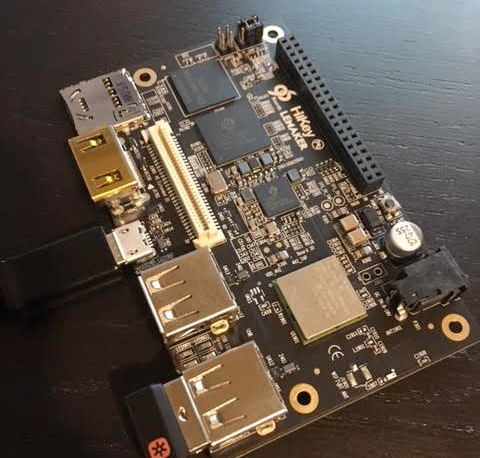
HiKey HiSilicon Kirin 620
This ARM Cortex-A53, 8-core, 2GB DDR3, board is amazing! I’m an entry-level ARM security enthusiast and this board feels like the perfect starting place for TrustZone and a secure/verified boot research. When the HiKey was first released I waited 3 months for my order to arrive. Last month, I waited only two days to ship from HK to California, way to go Seeed!
Hikey supports the ARM Trusted Firmware and OP-TEE reference specifications so we can clone from Github, compile, and flash rather effortlessly. We can write the secure ‘ROM’, secure world operating system, and the non-trusted firmware executing in the normal world.
To get started I reviewed “An Introduction to ARM Trusted Firmware for ARMv8-A” and a “Deep Dive into ARM Trusted Firmware” from LCU13, (YouTube), and pretended to comprehend the ARMv8-A Firmware Design guide. ;) My goal was to get hands-on experience with ARM TrustZone, secure world code, and the general firmware execution block diagrams.
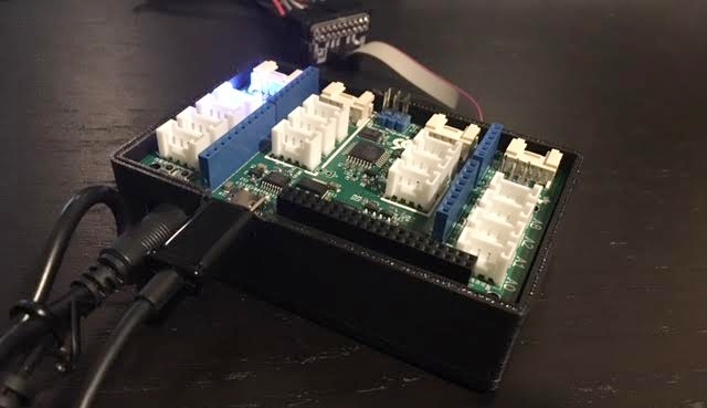
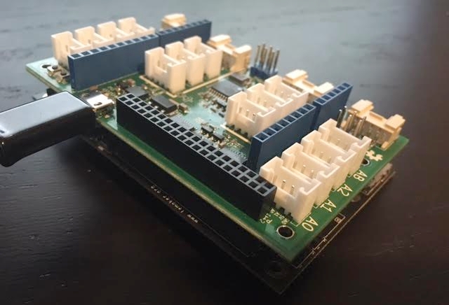
Completed HIkey with 96boards grooves expansion, uart0, jtag to busblaster, and 3d-printed housing.
HiKey reference materials:
- ARM Cortex-A53 Technical Reference Specification
- HiSilicon Kirin 622V100 Multi-Mode Application Processor
- HiKey User Guide
- 96Boards GitHub HiKey Wiki
Getting Started
This introduction is written as a tutorial, often in the simple future tense, please enjoy!
The first thing we’ll do is inspect the default state of the HiKey, using the 96Boards sensor expansion, we can attach to the UART3 breakout from the low speed (LS) expansion header.
A note about UARTs, In the documentation here, UART0 is as it appears without header in the HiKey user guide, This is NOT attached to the low-speed expansion connector. We wont have to pay too much attention as the HiKey’s UART3 will be the default. Some more-generic 96Boards documentation will refer to the “default” UART as UART0, this is UART3 on the HiKey, TL;DR, we don’t have to worry about modifying build/firmware variables to get debug output over serial.
Attaching the HiKey’s UART3 to my desktop:
$ dmesg
[...]
usb 1-2: new full-speed USB device number 126 using xhci_hcd
usb 1-2: New USB device found, idVendor=0403, idProduct=6015
usb 1-2: New USB device strings: Mfr=1, Product=2, SerialNumber=3
usb 1-2: Product: FT230X 96Boards Console
usb 1-2: Manufacturer: FTDI
usb 1-2: SerialNumber: DA71MVG
ftdi_sio 1-2:1.0: FTDI USB Serial Device converter detected
usb 1-2: Detected FT-X
usb 1-2: FTDI USB Serial Device converter now attached to ttyUSB0
And then using: $ sudo screen /dev/ttyUSB0 115200 we’ll quickly see:
NOTICE:  Booting Trusted Firmware
NOTICE:  BL1: v1.1(release):e9b4909
NOTICE:  BL1: Built : 10:50:16, Nov 28 2015
NOTICE:  syspll frequency:1190494208Hz
NOTICE:  succeed to init lpddr3 rank0 dram phy
INFO:    lpddr3_freq_init, set ddrc 533mhz
INFO:    init ddr3 rank0
INFO:    ddr3 rank1 init pass
INFO:    lpddr3_freq_init, set ddrc 800mhz
INFO:    init ddr3 rank0
INFO:    ddr3 rank1 init pass
INFO:    Samsung DDR
NOTICE:  BL1: Booting BL2
NOTICE:  acpu_dvfs_set_freq: set acpu freq success!NOTICE:  BL2: v1.1(release):e9b4909
NOTICE:  BL2: Built : 10:50:16, Nov 28 2015
NOTICE:  BL1: Booting BL3-1
NOTICE:  BL3-1: v1.1(release):e9b4909
NOTICE:  BL3-1: Built : 10:50:16, Nov 28 2015
UEFI firmware (version PreAlpha built at 10:50:05 on Nov 28 2015)
Followed by several _clear_s, then GRUB, with the quick-default option to boot a Linux Kernel from the eMMC flash.
At the root> prompt, we can inspect the first bits of dmesg:
(hikey)$ dmesg
[    0.000000] Linux version 3.18.0-linaro-hikey (buildslave@x86-64-07) (gcc version 5.1.1 20150608 (Linaro GCC 5.1-2015.08) ) #1 SMP PREEMPT Mon Nov 30 00:11:03 UTC 2015
[    0.000000] CPU: AArch64 Processor [410fd033] revision 3
[    0.000000] Detected VIPT I-cache on CPU0
[    0.000000] efi: Getting EFI parameters from FDT:
[    0.000000] EFI v2.40 by Linaro HiKey EFI Nov 28 2015 10:50:07
[    0.000000] efi:
[    0.000000] cma: Reserved 128 MiB at 0x0000000072c00000
[    0.000000] On node 0 totalpages: 515598
[    0.000000]   DMA zone: 7168 pages used for memmap
[    0.000000]   DMA zone: 0 pages reserved
[    0.000000]   DMA zone: 515598 pages, LIFO batch:31
[    0.000000] psci: probing for conduit method from DT.
[    0.000000] psci: PSCIv1.0 detected in firmware.
[    0.000000] psci: Using standard PSCI v0.2 function IDs
[    0.000000] PERCPU: Embedded 14 pages/cpu @ffffffc07f68f000 s19328 r8192 d29824 u57344
[    0.000000] pcpu-alloc: s19328 r8192 d29824 u57344 alloc=14*4096
[    0.000000] pcpu-alloc: [0] 0 [0] 1 [0] 2 [0] 3 [0] 4 [0] 5 [0] 6 [0] 7
[    0.000000] Built 1 zonelists in Zone order, mobility grouping on.  Total pages: 508430
[    0.000000] Kernel command line: BOOT_IMAGE=/boot/Image console=tty0 console=ttyAMA3,115200 root=/dev/disk/by-partlabel/system rootwait rw quiet efi=noruntime
[...]
Then inspect the mounted partitions:
(hikey)$ mount | grep mmc
/dev/mmcblk0p9 on / type ext4 (rw,relatime,data=ordered)
/dev/mmcblk0p6 on /boot/efi type vfat (rw,relatime,fmask=0022,dmask=0022,codepage=437,iocharset=iso8859-1,shortname=mixed,errors=remount-ro)
And the eMMC partition table:
(hikey)$ sudo partx -s /dev/mmcblk0
NR   START      END  SECTORS SIZE NAME       UUID
 1    2048     4095     2048   1M vrl        496847ab-56a1-4cd5-a1ad-47f4acf055c9
 2    4096     6143     2048   1M vrl_backup 61a36fc1-8efb-4899-84d8-b61642efa723
 3    6144     8191     2048   1M mcuimage   65007411-962d-4781-9b2c-51dd7df22cc3
 4    8192    24575    16384   8M fastboot   496847ab-56a1-4cd5-a1ad-47f4acf055c9
 5   24576    28671     4096   2M nvme       00354bcd-bbcb-4cb3-b5ae-cdefcb5dac43
 6   28672   159743   131072  64M boot       5c0f213c-17e1-4149-88c8-8b50fb4ec70e
 7  159744   684031   524288 256M reserved   bed8ebdc-298e-4a7a-b1f1-2500d98453b7
 8  684032  1208319   524288 256M cache      a092c620-d178-4ca7-b540-c4e26bd6d2e2
 9 1208320 15269854 14061535 6.7G system     fc56e345-2e8e-49ae-b2f8-5b9d263fe377
The sector size is 512, and there’s a 1M partition table starting at 0x0 not shown in the output. I prefer to backup the partitions I intend to overwrite while firmware testing, in this case the first 6 and the partition table.
(hikey)$ ls -la p*
-rw-r--r-- 1 root root  1048576 Jul  3 19:13 p1-vrl
-rw-r--r-- 1 root root  1048576 Jul  3 19:13 p2-vrl_backup
-rw-r--r-- 1 root root  1048576 Jul  3 19:13 p3-mcuimage
-rw-r--r-- 1 root root  8388608 Jul  3 19:13 p4-fastboot
-rw-r--r-- 1 root root  2097152 Jul  3 19:14 p5-nvme
-rw-r--r-- 1 root root 67108864 Jul  3 19:14 p6-boot
-rw-r--r-- 1 root root  1048576 Jul  3 19:13 ptable
(hikey)$ shasum -a 256 p*
30e14955ebf1352266dc2ff8067e68104607e750abb9d3b36582b8af909fcb58  p1-vrl
30e14955ebf1352266dc2ff8067e68104607e750abb9d3b36582b8af909fcb58  p2-vrl_backup
30e14955ebf1352266dc2ff8067e68104607e750abb9d3b36582b8af909fcb58  p3-mcuimage
9b0cae2b0493cccdc567e47a5551bfafcaea8f755e8f7e846f18c480d8e0dd25  p4-fastboot
2be59aabcf443128027ce62eb19a77fc7efa13c231e2045bb03bb427751fb96f  p5-nvme
b9744564bad753f69699be9a1484e3a8460ea271e076a5c7f2849ec7182a4224  p6-boot
7b95a7543fd61219bfa9ecb5f98fbe7418b8181f4acb14f214d6ce4c3865eb45  ptable
The first 3 partitions (vrl, vrl_backup, and mcuimage) are empty, and the hashes should be deterministic across reboots.
We’ll want to back up the “Alternate boot option”, or “Fast boot”, or “Boot mode” areas from the eMMC, which Linux makes available as /dev/mmcblk0boot{0,1} too! These “partitions” are essentially other block devices accessed through configuration registers in the eMMC PROM.
Awesome! Feel free to play around, I updated and removed the desktop manager as well as installed a Ubuntu-core to an SD card and attempted to boot that. Network manager is somewhat clunky yet it is possible to auto-associate with a personal WPA2 on boot for SSH access. When you feel at home let’s continue with loading our own firmware.
NB, to configure NetworkManager really fast:
nmcli con add con-name NETWORK-NAME ifname wlan1 type wifi ssid NETWORK-NAME ip4 192.168.0.120/24 gw4 192.168.0.1
nmcli con modify NETWORK-NAME wifi-sec.key-mgmt wpa-psk
nmcli con modify NETWORK-NAME wifi-sec.psk "SHARED-KEY"
nmcli con modify NETWORK-NAME ipv4.dns "8.8.8.8 8.8.4.4"
nmcli con up NETWORK-NAME
Build and compile firmware
When playing with firmware on new devices I have a few curiosities:
- Assuming physical access, what is the first instruction I can modify?
- What hardware strapping/jumpers exist to change that default “first instruction”?
- What firmware or loader does the CPU expect to jump into?
That last question is important, for the HiKey the recommended first is l-loader to immediately place the CPU into AArch64 mode. According to the HiKey User Guide: “(default) the unit boots from the first stage bootloader installed in the onboard eMMC device.” The l-loader will also contain the ARM “Secure ROM”, or BL1, code.
But in section 7 P2 - uSD CARD Socket “An ALPS micro SDHC card socket P2, part number SCHA4B0415, is installed on the HiKey board on the bottom left corner of the PCB. If a suitable bootloader is installed and a bootable microSD card is installed at power up, the HiKey board can boot from software installed on the microSD card and not the default OS stored in the on-board eMMC flash memory.”, and in section 1.6 Boot Mechanism of the Hi622v100 SoC documentation we see “The Hi6220 can boot from the on-chip BOOTROM (bootstrap mode), eMMC, which depends on the inputs of the BOOT_SEL and NAND_BOOT pins and eFUSE configurations.”, interesting! This is a development board, so boot flexibility is always preferred. Let’s make a note to investigate and inspect this “alternate-default” boot path later. The security_boot_flg eFUSE configuration is also worth revisiting.
To clarify the Application Processor documentation’s BOOT_SEL==1 means an open Boot Select from the HiKey documentation. This is the default state, where the BOOTROM is selected from the onboard eMMC flash.
To summarize, there’s some missing information about how the SoC can select the uSD as its default boot target. And missing information about boot-related eFUSEs and where on the SoC the l-loader is stored. But let’s not worry about that now.
HiKey provides a wonderful guide on creating a build environment for their firmware. Let’s follow it almost exactly.
sudo pip install wand

wget http://releases.linaro.org/15.02/components/toolchain/binaries/aarch64-linux-gnu/gcc-linaro-4.9-2015.02-3-x86_64_aarch64-linux-gnu.tar.xz
wget http://releases.linaro.org/15.02/components/toolchain/binaries/arm-linux-gnueabihf/gcc-linaro-4.9-2015.02-3-x86_64_arm-linux-gnueabihf.tar.xz

mkdir arm-tc arm64-tc
tar --strip-components=1 -C ${PWD}/arm64-tc -xf gcc-linaro-4.9-*-x86_64_aarch64-linux-gnu.tar.xz
tar --strip-components=1 -C ${PWD}/arm-tc -xf gcc-linaro-4.9-*-x86_64_arm-linux-gnueabihf.tar.xz
export PATH="${PWD}/arm-tc/bin:${PWD}/arm64-tc/bin:$PATH"
Now for the various firmware repositories
git clone -b hikey https://github.com/96boards/edk2.git linaro-edk2
git clone -b hikey https://github.com/96boards-hikey/arm-trusted-firmware.git
git clone -b hikey https://github.com/96boards/LinaroPkg.git
git clone https://github.com/96boards/l-loader.git
git clone git://git.linaro.org/uefi/uefi-tools.git
git clone https://github.com/OP-TEE/optee_os.git
The guide also provides a build script, let’s open and write build.sh:
#!/bin/bash

export PATH="${PWD}/arm-tc/bin:${PWD}/arm64-tc/bin:$PATH"
export AARCH64_TOOLCHAIN=GCC49
export EDK2_DIR=${PWD}/linaro-edk2
export UEFI_TOOLS_DIR=${PWD}/uefi-tools

cd ${EDK2_DIR}
${UEFI_TOOLS_DIR}/uefi-build.sh -c ../LinaroPkg/platforms.config -b RELEASE -a ../arm-trusted-firmware -s ../optee_os hikey

cd ../l-loader
ln -fs ${EDK2_DIR}/Build/HiKey/RELEASE_GCC49/FV/bl1.bin
ln -fs ${EDK2_DIR}/Build/HiKey/RELEASE_GCC49/FV/fip.bin
arm-linux-gnueabihf-gcc -c -o start.o start.S
arm-linux-gnueabihf-gcc -c -o debug.o debug.S
arm-linux-gnueabihf-ld -Bstatic -Tl-loader.lds -Ttext 0xf9800800 start.o debug.o -o loader
arm-linux-gnueabihf-objcopy -O binary loader temp
python gen_loader.py -o l-loader.bin --img_loader=temp --img_bl1=bl1.bin

# sgdisk usage requires sudo
sudo PTABLE=linux-4g bash -x generate_ptable.sh
python gen_loader.py -o ptable-linux.img --img_prm_ptable=prm_ptable.img
Your directory setup will look similar to:
ls -l /opt/hikey
total 65760
drwxrwxr-x  8 4096 20:13 arm64-tc
drwxrwxr-x  8 4096 20:07 arm-tc
drwxrwxr-x 17 4096 20:25 arm-trusted-firmware
-rwxrwxr-x  1 1331 13:07 build.sh
drwxrwxr-x 42 4096 21:49 linaro-edk2
drwxrwxr-x  3 4096 13:42 LinaroPkg
drwxrwxr-x  3 4096 13:43 l-loader
drwxrwxr-x 11 4096 21:56 optee_os
drwxrwxr-x  3 4096 13:19 uefi-tools
Let’s execute ./build.sh and notice at the end of uefi-tools/uefi-build.sh:
Built build/hikey/release/bl2.bin successfully
Built build/hikey/release/bl1.bin successfully

  LD      fip_create

Built fip_create successfully

  LD      build/hikey/release/bl31/bl31.elf
  OD      build/hikey/release/bl31/bl31.dump
  BIN     build/hikey/release/bl31.bin

Built build/hikey/release/bl31.bin successfully

Firmware Image Package ToC:
---------------------------
- Trusted Boot Firmware BL2: offset=0x100, size=0x7100
  file: './build/hikey/release/bl2.bin'
- EL3 Runtime Firmware BL3-1: offset=0x7200, size=0x7010
  file: './build/hikey/release/bl31.bin'
- Secure Payload BL3-2 (Trusted OS): offset=0xE210, size=0x361C4
  file: '/opt/hikey/linaro-edk2/Build/HiKey/RELEASE_GCC49/FV/tee.bin'
- SCP Firmware BL3-0: offset=0x443D4, size=0x23D00
  file: '/opt/hikey/linaro-edk2/HisiPkg/HiKeyPkg/NonFree/mcuimage.bin'
- Non-Trusted Firmware BL3-3: offset=0x680D4, size=0xF0000
  file: '/opt/hikey/linaro-edk2/Build/HiKey/RELEASE_GCC49/FV/BL33_AP_UEFI.fd'
---------------------------
Creating "build/hikey/release/fip.bin"
We don’t need to do anything more in the guide, we have our:
l-loader/l-loader.binl-loader/fip.bin- An updated partition table
l-loader/ptable-linux.img
Components of the HiKey firmware
The components, stages, and references here are very well summarized in the ARM Trusted Firmware Design document. Below we’ll briefly map the downloaded and compiled components.
The following components can be found in the fip.bin:
BL2:./arm-trusted-firmware/build/hikey/release/bl2.binBL3-0:./linaro-edk2/HisiPkg/HiKeyPkg/NonFree/mcuimage.binBL3-1:./arm-trusted-firmware/build/hikey/release/bl31.binBL3-2:./linaro-edk2/Build/HiKey/RELEASE_GCC49/FV/tee.binBL3-3:./linaro-edk2/Build/HiKey/RELEASE_GCC49/FV/BL33_AP_UEFI.fd
BL1 and the code from ./l-loader/start.S are written to l-loader.bin.
l-loader
The l-loader code is fairly small, check out the l-loader/start.S code to inspect what the CPU is jumping into immediately on boot at 0xF9800800. The included loader script places bl1.bin at 0xF9801000. It seems the 0xF980:0000 MMIO area is mapped by the memory controller from the eMMC alternate boot option by default (just a guess, I cannot find this in the SoC or AP documentation).
BL1: AP Trusted ROM
On the HiKey this is loaded from 0xF9800000 + 0x1000.
To borrow from the guide, BL1 performs the following initializations:
- Enable the Trusted Watchdog.
- Initialize the console.
- Configure the Interconnect to enable hardware coherency.
- Enable the MMU and map the memory it needs to access.
- Configure any required platform storage to load the next bootloader image (
BL2).
We can find the implementation code:
./arm-trusted-firmware/bl1
./arm-trusted-firmware/plat/hikey/
BL2: Trusted Boot Firmware
BL2 performs the following initializations:
- Initialize the console.
- Configure any required platform storage to allow loading further bootloader images.
- Enable the MMU and map the memory it needs to access.
- Perform platform security setup to allow access to controlled components.
- Reserve some memory for passing information to the next bootloader image EL3 Runtime Software and populate it.
- Define the extents of memory available for loading each subsequent bootloader image.
We can find the implementation code:
./arm-trusted-firmware/bl2
./arm-trusted-firmware/bl2/bl2-main.c
This stage may also load a platform-specific (optional) binary into a region of secure memory. It doesn’t seem the HiKey is using a SCP_BL2, but if it did that optional image would execute and eventually return executing to BL2.
This stage is responsible for loading:
BL31(EL3)into trusted SRAM.- An optional
BL32into a region of secure memory, to later execute in the secure world. BL33into non-secure memory.
When finished, BL2 will pass control back to BL1 using an SMC call and the BL31 loaded entrypoint. BL1 is then responsible for jumping and executing BL31 within trusted SRAM. The HiKey is using a SCP and calling it BL3-0.
We can find the non-free binary for BL3-0:
./linaro-edk2/HisiPkg/HiKeyPkg/NonFree/mcuimage.bin
BL31: EL3 Runtime Software
As described in the guide, BL31 is very similar to BL1 and may replace most of its initialization. On a secured system the BL1 code is a ROM, thus EL3 may field update and boot time patch when changes are needed.
BL31 performs the following initializations:
- Initialize the console.
- Configure the Interconnect to enable hardware coherency.
- Enable the MMU and map the memory it needs to access.
- Initialize the generic interrupt controller.
- Initialize the power controller device.
- Detect the system topology.
That last line includes the runtime services initialization. BL31 then executes BL32 if it exists. This phase uses the information provides by BL2 to locate and execute the BL33 normal-world firmware. In our current state, the UEFI platform code.
We can find the implementation code:
./arm-trusted-firmware/bl31/
BL32: Secure-EL1 Payload (optional)
This is the optional Trusted OS running in the secure world setup and implemented using the runtime services in BL31 where communication occurs using the SMCs installed also in BL31.
We replace the Test secure world OS included with arm-trusted-firmware with OP-TEE. This replacement is seen in the build script above using the -s switch.
We can find the implementation code:
./optee_os/
BL33: Non-trusted Firmware (UEFI)
And finally the UEFI code is provided by ./linaro-edk2.
Flashing the Firmware
We need the fastboot tool:
sudo apt-get install fastboot
And the HiSilicon loader flasher:
wget https://raw.githubusercontent.com/96boards/burn-boot/master/hisi-idt.py
Now we need to put the device into recovery mode by changing the BOOT_SEL jumper and connecting to the HiKey USB OTG.
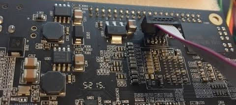
The recovery-mode is accessed via the USB OTG when the BOOT_SEL and autoboot (TOP) JUMPERs are closed.
I’ll remove the 96Boards signals expansion to clearly show the OTG and jumper configuration (Pins 1-2 Autoboot closed, pins 3-4 Boot select closed, pins 5-6 open). The board must be supplied power, keeping the barrel connector in is fine.
On my desktop I see:
usb 1-2: new full-speed USB device number 127 using xhci_hcd
usb 1-2: New USB device found, idVendor=12d1, idProduct=3609
usb 1-2: New USB device strings: Mfr=1, Product=4, SerialNumber=0
usb 1-2: Product: \xffffffe3\xffffff84\xffffffb0㌲㔴㜶㤸
usb 1-2: Manufacturer: 䕇䕎䥎
usbserial: USB Serial support registered for GSM modem (1-port)
option 1-2:1.0: GSM modem (1-port) converter detected
usb 1-2: GSM modem (1-port) converter now attached to ttyUSB0
To flash the l-loader and BL1 to 0xF9800800:
$ sudo python hisi-idt.py --img1=./l-loader/l-loader.bin
+----------------------+
(' Serial: ', '/dev/serial/by-id/usb-\xe4\x95\x87\xe4\x95\x8e\xe4\xa5\x8e_\xe3\x84\xb0\xe3\x8c\xb2\xe3\x94\xb4\xe3\x9c\xb6\xe3\xa4\xb8-if00-port0')
(' Image1: ', './l-loader/l-loader.bin')
(' Image2: ', '')
+----------------------+

('Sending', './l-loader/l-loader.bin', '...')
Done
The only documentation I have on the 0xF9800:0000 mapping is that it is missing from the HiSilicon guide, from page 225:
Module    Size  Base        Width
BOOTROM   32K   0xFFFF0000  32
SRAM_OFF  72K   0xFFF80000  32
UART0     4KB   0xF8015000  32
[...]
To flash the fip.bin and remaining stages to the eMMC:
$ sudo fastboot flash ptable l-loader/ptable-linux.img
target reported max download size of 268435456 bytes
sending 'ptable' (17 KB)...
OKAY [  0.001s]
writing 'ptable'...
OKAY [  0.002s]
finished. total time: 0.002s

$ sudo fastboot flash fastboot l-loader/fip.bin
target reported max download size of 268435456 bytes
sending 'fastboot' (1376 KB)...
OKAY [  0.035s]
writing 'fastboot'...
OKAY [  0.035s]
finished. total time: 0.070s
Booting updated firmware
Now to boot our updated firmware:
- Unplug the HiKey.
- Remove the
BOOT_SELjumper between pins 3-4. - Attach your 96Boards signal expansion or UART breakout.
- Attach to the UART from on your desktop:
sudo screen /dev/ttyUSB0 115200 - Restore power to the HiKey.
We should be greeted with updated times and revisions:
NOTICE:  Booting Trusted Firmware
NOTICE:  BL1: v1.1(release):167e4ed
NOTICE:  BL1: Built : 16:59:44, Nov 20 2016
NOTICE:  syspll frequency:1190494208Hz
NOTICE:  succeed to init lpddr3 rank0 dram phy
INFO:    lpddr3_freq_init, set ddrc 533mhz
INFO:    init ddr3 rank0
INFO:    ddr3 rank1 init pass
INFO:    lpddr3_freq_init, set ddrc 800mhz
INFO:    init ddr3 rank0
INFO:    ddr3 rank1 init pass
INFO:    Samsung DDR
NOTICE:  BL1: Booting BL2
NOTICE:  acpu_dvfs_set_freq: set acpu freq success!
NOTICE:  BL2: v1.1(release):167e4ed
NOTICE:  BL2: Built : 16:59:44, Nov 20 2016
NOTICE:  BL1: Booting BL3-1
NOTICE:  BL3-1: v1.1(release):167e4ed
NOTICE:  BL3-1: Built : 16:59:44, Nov 20 20
INFO:    TEE-CORE: Initializing (2.2.0-89-gaae611c #1 Mon Nov 21 00:59:42 UTC 2016 aarch64)
INFO:    TEE-CORE: Initialized
UEFI firmware (version PreAlpha built at 16:59:29 on Nov 20 2016)
And booting Linux should also tell us: EFI v2.40 by Linaro HiKey EFI Nov 20 2016 16:59:32.
Building DEBUG Firmware
This wasn’t as straightforward as I hoped. Please take these suggestions with a grain of salt and verify the output is a debug build. I ended up “forcing” the build-type in several areas.
First modify ./build.sh and verify that linaro-edk2/Build/HiKey/DEBUG_GCC49 contains the firmware volume output:
# Add this "build type"
BUILD=DEBUG

cd ${EDK2_DIR}
if [[ "$BUILD" = "DEBUG" ]]; then
    export DEBUG=1
fi
${UEFI_TOOLS_DIR}/uefi-build.sh -c ../LinaroPkg/platforms.config -b $BUILD -a ../arm-trusted-firmware -s ../optee_os hikey

cd ../l-loader
ln -fs ${EDK2_DIR}/Build/HiKey/${BUILD}_GCC49/FV/bl1.bin
ln -fs ${EDK2_DIR}/Build/HiKey/${BUILD}_GCC49/FV/fip.bin
Now modify the OP-TEE profile in./LinaroPkg:
diff --git a/platforms.config b/platforms.config
index 2db0d24..0bacd63 100644
--- a/platforms.config
+++ b/platforms.config
@@ -105,17 +105,18 @@ DSC=HisiPkg/HiKeyPkg/HiKey.dsc
 ARCH=AARCH64
 UEFI_BIN=BL33_AP_UEFI.fd
 UEFI_IMAGE_DIR=HiKey
-BUILD_ATF=yes
+BUILD_ATF=debug
 ATF_SPD=opteed
 TOS_BIN=tee.bin
-BUILD_TOS=yes
+BUILD_TOS=debug
+

 SCP_BIN=HisiPkg/HiKeyPkg/NonFree/mcuimage.bin
And verify the new output from the build script:
Building opteed Trusted OS
Target: AARCH64
Build: other
Target: ARM
Build: other
CFG_ARM64_core=y
CROSS_COMPILE_ta_arm64=aarch64-linux-gnu-
CROSS_COMPILE=arm-linux-gnueabihf-
CROSS_COMPILE_core=aarch64-linux-gnu-
PROFILE=DEBUG
PLATFORM=hikey
PLATFORM_FLAVOR=
CFG_TEE_CORE_LOG_LEVEL=2
[...]
Target: AARCH64
Build: other
Building ARM Trusted Firmware for CircuitCo HiKey - DEBUG_GCC49
CROSS_COMPILE="aarch64-linux-gnu-"
BL30=/opt/hikey/linaro-edk2/HisiPkg/HiKeyPkg/NonFree/mcuimage.bin
BL31=
BL32=/opt/hikey/linaro-edk2/Build/HiKey/DEBUG_GCC49/FV/tee.bin
BL33=/opt/hikey/linaro-edk2/Build/HiKey/DEBUG_GCC49/FV/BL33_AP_UEFI.fd
SPD=opteed
BUILD_TYPE=debug
The final Table of Contents should resemble:
Firmware Image Package ToC:
---------------------------
- Trusted Boot Firmware BL2: offset=0x100, size=0x9100
  file: './build/hikey/debug/bl2.bin'
- EL3 Runtime Firmware BL3-1: offset=0x9200, size=0xB010
  file: './build/hikey/debug/bl31.bin'
- Secure Payload BL3-2 (Trusted OS): offset=0x14210, size=0x4D244
  file: '/opt/hikey/linaro-edk2/Build/HiKey/DEBUG_GCC49/FV/tee.bin'
- SCP Firmware BL3-0: offset=0x61454, size=0x23D00
  file: '/opt/hikey/linaro-edk2/HisiPkg/HiKeyPkg/NonFree/mcuimage.bin'
- Non-Trusted Firmware BL3-3: offset=0x85154, size=0xF0000
  file: '/opt/hikey/linaro-edk2/Build/HiKey/DEBUG_GCC49/FV/BL33_AP_UEFI.fd'
---------------------------
Creating "build/hikey/debug/fip.bin"

Built build/hikey/debug/fip.bin successfully
JTAG the HiKey
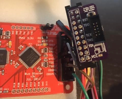
There is another wonderful guide about JTAGging the HiKey, this is why I love this platform, such amazing documentation. That guide includes notes for Dangerous Prototype’s Bus Blaster, a very handy device I’ll use in this exploration.
Soldering the JTAG breakout
What you’ll need:
- A Bus Blaster or equivalent JTAG interface
- Basic soldering skills
FTSH-105-01-L-DV-Kto attach to the HiKey- A SWD 10pin to 20pin JTAG breakout (if using the Bus Blaster)
- A SWD 10pin ribbon
I had the breakout and ribbon from my Black Magic Probe kit. :)
Soldering the FTSH-105-01-L-DV-K was easy, hold it in place with a finger and solder with an iron, some primed solder and flux.
The HiKey schematic very useful: https://www.96boards.org/wp-content/uploads/2015/02/96Boards-Hikey-Rev-A1.pdf
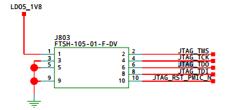
Knowing the pinout allowed me to trace each into the Bus Blaster’s breakout so I was absolutely sure I hadn’t attached a ribbon backward or soldered housing upside-down (it happens more often than it should in my life). I didn’t bother attaching power since the HiKey is self-powered and supplying too much voltage will brick your board.
Configuring the Bus Blaster
Plugging in the Bus Blaster’s USB to my desktop:
usb 1-9: new high-speed USB device number 6 using xhci_hcd
usb 1-9: New USB device found, idVendor=0403, idProduct=6010
usb 1-9: New USB device strings: Mfr=1, Product=2, SerialNumber=0
usb 1-9: Product: Dual RS232-HS
usb 1-9: Manufacturer: FTDI
ftdi_sio 1-9:1.0: FTDI USB Serial Device converter detected
usb 1-9: Detected FT2232H
usb 1-9: FTDI USB Serial Device converter now attached to ttyUSB1
ftdi_sio 1-9:1.1: FTDI USB Serial Device converter detected
usb 1-9: Detected FT2232H
usb 1-9: FTDI USB Serial Device converter now attached to ttyUSB2
Let’s compile openocd:
git clone https://git.linaro.org/people/peter.griffin/openocd-code
cd openocd-code
git checkout armv8
git submodule update --init --recursive
autoreconf -iv

mkdir ../openocd
./configure --enable-ftdi --prefix `realpath ../openocd`
make
make install
The HiKey guides tells us:
JP4, the target power select jumper, must be disconnected.- The BBv3 buffer logic must be programmed with SVF from https://github.com/bharrisau/busblaster.
git clone https://github.com/bharrisau/busblaster
cd busblaster
../openocd/bin/openocd -f board/dp_busblaster_v3.cfg -c "adapter_khz 1000; init; svf ./synthesis/system.svf; shutdown"
We should see output similar to:
Open On-Chip Debugger 0.9.0-dev-00001-g1bef29e (2016-11-20-18:58)
Licensed under GNU GPL v2
For bug reports, read
    http://openocd.sourceforge.net/doc/doxygen/bugs.html
Info : If you need SWD support, flash KT-Link buffer from https://github.com/bharrisau/busblaster
and use dp_busblaster_kt-link.cfg instead
Error: session transport was not selected. Use 'transport select <transport>'
Info : session transport was not selected, defaulting to JTAG
adapter speed: 1000 kHz
Info : clock speed 1000 kHz
Info : JTAG tap: xc2c32a.tap tap/device found: 0x06e1c093 (mfg: 0x049, part: 0x6e1c, ver: 0x0)
Warn : gdb services need one or more targets defined
svf processing file: "./synthesis/system.svf"
TRST OFF;
[...]
Time used: 0m0s652ms
svf file programmed successfully for 214 commands with 0 errors
shutdown command invoked
Attaching to the HiKey
Now we can use our compiled openocd and configured Bus Blaster:
export INTERFACE=interface/ftdi/dp_busblaster_kt-link.cfg
openocd/bin/openocd -f $INTERFACE -f target/hi6220.cfg
Open On-Chip Debugger 0.9.0-dev-00001-g1bef29e (2016-11-20-18:58)
Licensed under GNU GPL v2
For bug reports, read
    http://openocd.sourceforge.net/doc/doxygen/bugs.html
adapter speed: 10 kHz
jtag_ntrst_delay: 100
trst_and_srst combined srst_gates_jtag trst_push_pull srst_open_drain connect_deassert_srst
Info : clock speed 10 kHz
Info : JTAG tap: hi6220.dap tap/device found: 0x5ba00477 (mfg: 0x23b, part: 0xba00, ver: 0x5)
Info : hi6220.cpu: hardware has 6 breakpoints, 4 watchpoints
If the soldering or pinout was incorrect you may see results similar to:
Info : clock speed 10 kHz
Error: JTAG scan chain interrogation failed: all ones
Error: Check JTAG interface, timings, target power, etc.
Error: Trying to use configured scan chain anyway...
Error: hi6220.dap: IR capture error; saw 0x0f not 0x01
Warn : Bypassing JTAG setup events due to errors
Warn : Invalid ACK 0x7 in JTAG-DP transaction
If you see this, trace again, and really quick reflow the JTAG pads.
Open OpenOCD’s telnet interface:
$ telnet localhost 4444
Trying 127.0.0.1...
Connected to localhost.
Escape character is '^]'.
Open On-Chip Debugger
>
Try to halt the CPU:
> halt
number of cache level 2
cache l2 present :not supported
hi6220.cpu cluster 0 core 0 multi core
target state: halted
target halted in ARM64 state due to debug-request, current mode: EL2H
cpsr: 0x60000309 pc: 0x7ff421a8
MMU: enabled, D-Cache: enabled, I-Cache: enabled
Then inspect the CPU registers:
> reg
===== arm v8 registers
(34) x0 (/64): 0x0000000000000306 (dirty)
[...]
(58) x24 (/64): 0x000000007FF56584
(59) x25 (/64): 0x000000007FF565D3
(60) x26 (/64): 0x000000007FF56599
(61) x27 (/64): 0x000000003DBF7531
(62) x28 (/64): 0x000000003DBF7525
(63) x29 (/64): 0x0000000000000000
(64) x30 (/64): 0x000000007FF42184
(65) sp (/64): 0x000000003DFFF9B0
(66) pc (/64): 0x000000007FF421A8
(67) CPSR (/32): 0x60000309
Finally, let’s break and step:
> bp 0x7ff421a8 4 hw
breakpoint set at 0x        7ff421a8
> resume
target state: halted
target halted in ARM64 state due to breakpoint, current mode: EL2H
cpsr: 0x60000309 pc: 0x7ff421a8
MMU: enabled, D-Cache: enabled, I-Cache: enabled
> step
target state: halted
target halted in ARM64 state due to breakpoint, current mode: EL2H
cpsr: 0x60000309 pc: 0x7ff421a8
MMU: enabled, D-Cache: enabled, I-Cache: enabled
timeout waiting for target halt
in procedure 'step'
Run-time flashing
As an aside, we can read the l-loader and BL1 MMIO area (0xF980:0800) on the booted HiKey using:
#include <stdio.h>
#include <stdlib.h>
#include <unistd.h>
#include <fcntl.h>
#include <errno.h>
#include <sys/mman.h>
#include <inttypes.h>

int main(int argc, char **argv)
{
    uint64_t target = 0xf9800000;
    uint64_t size = 0xf000;

    unsigned int pagesize = (unsigned)getpagesize(); /* or sysconf(_SC_PAGESIZE)  */
    unsigned int map_size = pagesize;

    unsigned offset = (unsigned int)(target & (pagesize-1));
    if (offset + 4 > pagesize ) {
        // Access straddles page boundary:  add another page:
        map_size += pagesize;
    }

    int fd = open("/dev/mem", O_RDWR | O_SYNC);
    if (fd == -1) {
        printf("Error opening /dev/mem (%d)\n", errno);
        exit(1);
    }

    void *map_base, *virt_addr;
    map_base = mmap(0, size, PROT_READ | PROT_WRITE, MAP_SHARED,
                    fd,
                    target & ~((typeof(target))pagesize-1));
    if (map_base == (void *) -1) {
        printf("Error mapping (%d)\n", errno);
        exit(1);
    }

    virt_addr = map_base + offset;
    FILE* in = fopen("output.bin", "wb");
    fwrite((uint8_t *) virt_addr, size, 1, in);

    fclose(in);
    munmap(map_base, size);
    close(fd);

    return 0;
}
We should see our l-loader.bin when hexdump -C output.bin | less:
00000800  3e 00 00 ea 42 4f 4f 54  4d 41 47 49 43 4e 55 4d  |>...BOOTMAGICNUM|
00000810  42 45 52 21 00 08 80 f9  00 ea 80 f9 45 4e 54 52  |BER!........ENTR|
00000820  59 48 44 52 6c 6f 61 64  65 72 00 00 04 00 00 00  |YHDRloader......|
00000830  02 00 00 00 01 00 00 00  45 4e 54 52 59 48 44 52  |........ENTRYHDR|
00000840  62 6c 31 00 00 00 00 00  08 00 00 00 6d 00 00 00  |bl1.........m...|
00000850  01 00 00 00 00 00 00 00  00 00 00 00 00 00 00 00  |................|
00000860  00 00 00 00 00 00 00 00  00 00 00 00 00 00 00 00  |................|
[...]
Let’s see if we can flip a byte: sudo devmem -r 0xF980B730 b 0x56. This should change ‘v1.1’ to ‘V1.1’. But this change doesn’t persist, ha!
We should also see the contents at offset 0x0800 on the /dev/mmcblk0boot0 device in Linux:
(hikey)$ sudo dd if=/dev/mmcblk0boot0 of=/tmp/boot0 bs=512
8192+0 records in
8192+0 records out
4194304 bytes (4.2 MB) copied, 0.299964 s, 14.0 MB/s
(hikey)$ hexdump -C /tmp/boot0 | head -n 10
00000000  00 00 00 00 00 00 00 00  00 00 00 00 00 00 00 00  |................|
*
00000800  3e 00 00 ea 42 4f 4f 54  4d 41 47 49 43 4e 55 4d  |>...BOOTMAGICNUM|
00000810  42 45 52 21 00 08 80 f9  00 ea 80 f9 45 4e 54 52  |BER!........ENTR|
00000820  59 48 44 52 6c 6f 61 64  65 72 00 00 04 00 00 00  |YHDRloader......|
00000830  02 00 00 00 01 00 00 00  45 4e 54 52 59 48 44 52  |........ENTRYHDR|
00000840  62 6c 31 00 00 00 00 00  08 00 00 00 6d 00 00 00  |bl1.........m...|
00000850  01 00 00 00 00 00 00 00  00 00 00 00 00 00 00 00  |................|
00000860  00 00 00 00 00 00 00 00  00 00 00 00 00 00 00 00  |................|
*
We can persist changes to the l-loader and BL1 code by writing back to the Alternate Boot option:
(hikey)$ echo 0 | sudo tee /sys/block/mmcblk0boot0/force_ro
0
(hikey)$ printf '\x56' | sudo dd conv=notrunc of=/tmp/boot0 bs=1 seek=$((0xb730))
(hikey)$ sudo dd if=/tmp/boot0 of=/dev/mmcblk0boot0 bs=512
8192+0 records in
8192+0 records out
4194304 bytes (4.2 MB) copied, 0.876785 s, 4.8 MB/s
Then reboot and check for a capital V:
NOTICE:  Booting Trusted Firmware
NOTICE:  BL1: V1.1(debug):167e4ed
NOTICE:  BL1: Built : 20:34:57, Nov 20 2016
INFO:    BL1: RAM 0xf9810000 - 0xf9818000